Radio Controlled Models
Share RCScrapyard on Facebook
RCScrapyard Radio Controlled Models
Flags
RCScrapyard.net contains Google and Amazon Affiliate links, which may earn us commission. See our Disclosure page for more info.
bar

Tamiya M26 Pershing - RTR - # 23618 (Radio Controlled Model Review)

1/16 Scale Electric Tank -


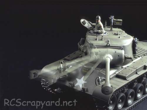
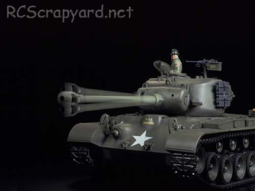
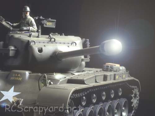
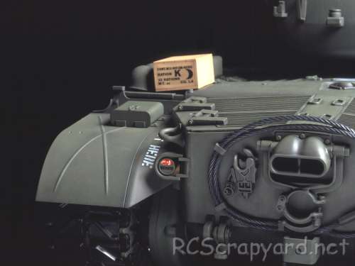
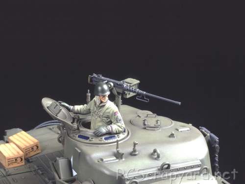
  Released by Tamiya on March 1, 2005, the M26 Pershing - US Medium Tank T26E3 (# 23618) is the Factory Finished, Limited Edition RTR version.

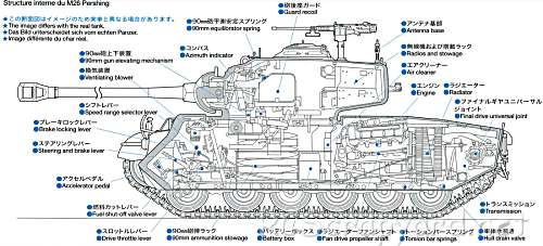
  A front-mounted double gearbox, with two electric motors, operate together or individually to produce forward/reverse running and pivot turning. Metal torsion bars and suspension arms combine with the wide tracks to smoothly absorb bumps and dips in the terrain and provide high manoeuvrability. In addition, realistic engine sounds accompany the tank as it starts up, drives and stops to idle. The main gun can be elevated, depressed and swung to the left and right.

Tamiya M26 Pershing - # 56016

▼ Scroll Down for More Images ▼


  The M26 Pershing was a heavy/medium tank of the US Army. Named after General John J. Pershing, famous for his exploits in World War I. It was briefly used in the final months of World War II during the Invasion of Germany and extensively during the Korean War.

  Intended as a replacement for the M4 Sherman, the prolonged time of development meant that only a small number saw combat in the Europe, most notably in the 9th Armored Division's dramatic dash to take the Ludendorff Bridge during the Battle of Remagen. In service during the Korean War, the M26 outmatched the T-34-85 in terms of firepower and protection, but was challenged by the hilly and muddy terrain and as a result was withdrawn in 1951. The lineage of the M26 continued with the M47 Patton and was reflected in the new designs of the later M48 Patton and M60 Patton.

  This model comes with metal bushings, that after a short while, when dust and grit get into them, can actually wear into the metal drive shafts that spin in them - we recommend these should be replaced by a full set of steel shielded ball bearings ASAP.


Rating: 44 Stars out of 5 RCScrapyard


Gas/Nitro Engines Body Shells Radio Transmitters etc Tires Wheels/Rims Electronic Speed Controllers Battery Packs / Chargers Electric Motors


Flags


Tamiya M26 Pershing
Tamiya M26 Pershing
Tamiya M26 Pershing
Tamiya M26 Pershing
Tamiya M26 Pershing
Tamiya M26 Pershing
Tamiya M26 Pershing
Tamiya M26 Pershing
Tamiya M26 Pershing
Tamiya M26 Pershing
Tamiya M26 Pershing
Tamiya M26 Pershing

Hints, Tips and Information

How to avoid Radio Interference

1/  The first consideration when installing your Receiver into your Electrically Powered Model is to make sure it is well away from the Negative Battery terminal, and the Motor. The Magnetic field can cause stuttering type interference at times of high current draw (i.e., Fast Acceleration)

2/  Make sure the Ariel tube is long enough for the Ariel wire. The tip of this wire is highly sensitive and should be as high, and as far away from the Motor as possible (yup, its that magnetic field prob again)

3/  If all else fails, a simple tip that often works for all RC Model enthusiasts is to wrap the receiver in Aluminium Foil, to shield against any magnetic and external radio interference.

Read the Complete Article  ▶ ▶


Tamiya Buggys Tamiya Trucks Tamiya Monster Trucks Tamiya Rock Crawlers Tamiya Off Road Chassis Types Tamiya Touring Car Tamiya Drift Car Tamiya WRC Car Tamiya M Chassis
Tamiya Tractor Trucks Tamiya Touring Car Chassis Tamiya F1 Tamiya F1/Le Mans Chassis Types Tamiya Military Tamiya Tanks


Hints, Tips and Information

My First National

   When I first started in RC, way back in the late 1980s, I would turn up to the weekly club meeting, with my Tamiya Boomerang, Acoms transmitter, two sets of crystals, a couple of 7.2v batteries, a charger and a tool box with a wheel spanner and a few spares.
   It was three five minute qualifying rounds and a final, and every month we would have a trophy meeting. The trophies were donated by a two of the older semi professional guys who basically ran the club and over the years had collected what must have been hundreds of trophies and had no space for them anymore. The lure of a trophy always brought out the "not as enthusiastic types" and the small church function room was always packed on those nights.
   About a year in, my collection of B final trophies was beginning to clutter my room, and my dad bought me the new Tamiya Manta Ray. That was the big turning point in my RC career.
   From then on it was A finals all the way. Then one day in the summer of 1992 the club organisers (the semi pro guys) asked me if I would like to go to a BIG national meeting way down south in Malvern. I asked my dad and with a bit of prompting he said "why not".
   When we got to that meeting we found there were around a hundred competitors, with ten groups of ten. I was in group "H". a two of my friends went down with us and they were in group "I" so were on just before me.

Read the Complete Article  ▶ ▶


Information and Advice

Electronic Speed Controllers

History

   ESC were originally developed to be used in conjunction with brushed 27T stock and modified motors in the late 1970s, early 1980s. Compared to modern day Controllers, they were Bulky and heavy, constructed using basic resistors, rheostats, capacitors and transistors, crammed together on a simple circuit board, to provide stepped but smooth acceleration when compared to the old mechanical, servo operated sweeper Speed Controllers. An Electronic Switch to change the direction of current flow was used on some of these early ESC to give reverse operation. Although they were a vast improvement on the old mechanical speedos of the time, they were expensive, jerky to control, and prone to burn out if not carefully looked after.

   As new technology became available, improvements were slowly made, and with the introduction of the new FET (Field Effect Transistors) and some basic mass produced silicon chips, ESC were made smaller and their reliability gradually improved.

   By the mid 1990s, "regenerative breaking" was developed. This meant that energy that would have been lost slowing down the car by effectively turning the motor into a generator, was harvested and put back into the battery. This of course was long before F1 had KERS (Kinetic Energy Recovery System) and adjustable anti lock breaking was introduced.

Read the Complete Article  ▶ ▶


^ TOP ^

RC Models:
Radio
& Motors:
Other
Accessories: